Saturday 30 October 2010

Making it work!

Yesterday I managed to finish (as well as I could) my 'Robot Operation Game.' Now that the circuit was finally working I was able to test it out and see which cinductive material would work best and would be easiest to work with. I went thriugh a few materials that could have been used as the contact material of rthe buzzer to soun d but eventually settled with copper tape. The tape has a sticky side which sticks perfectly to acrylic so was ideal for the job.

To make a base for the robot and some spaces for the components to sit in I attempted to use the CNC machine. I thought it would be good to learn how to use this as I have never used one before. However, it didn't do the best job of it, the edges were left rough and the size was not accurate, and the shape I needed cutting could easily have been cut on the laser cutter.

I laser cut two more robot shapes for the middle and the base to give it some depth for the components to sit in...


This part will be sandwiched between the top etched robot shape and the plain base shape.


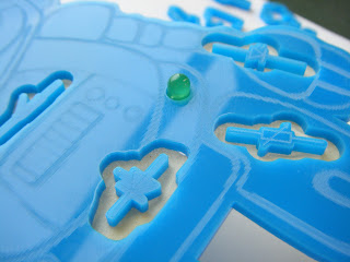
This is the base with a hole for the LED to fit into.


The next step was the stick on the copper tape as the conductive material which triggers the buzzer and LED when it's touched with the tweezers.


I first stuck on the copper tape to correspond with the holes in the robot for the components.


I then connected the areas with more copper tape so that all areas were linked. This was then tested with a micrometer to check the continuity across the tape but I found that the current would not flow along the paths to all the areas.


I then had to solder the copper paths to the copper areas to provide continuity across the base.


The yellow wire form the circuit board was then soldered to the top of the copper strips.


The base, middle and top of the robot were then stuck together with double sided tape which is strong enough to hold but is not permanent so that the robot could be fixed if it wasn't working:


The game is now fully working, which I am quite proud of! The circuit board will need some kind of box to encase it in just to protect it and keep it out of the way.


Thursday 28 October 2010

Completing the Circuit

I also managed to complete the Alarm Sensor Circuit today. This is another thing that took unnecessarily long!
I drilled all the holes for the components to go in and soldered them all on and...it didn't work. It took at least two hours to work out why it wasn't working and eventually I found that the copper track that I designed on Circuit Wizard was wrong! So after scratching off part of the track I managed to get it working:


Laser cutting

The image designed on 2D Design is now ready for etching and cutting. I managed to cut one version of the robot out at the elearning centre but it was slightly too small and it needed a hole for the LED to show through. So today I endeavoured to cut out another, bigger version. This was quite a mission as the laser cutter stopped working half way through and it took a while before it was fixed again. But I got it done in the end.

The component symbols are the bits to be extracted from the robot.


This LED will light up when the metal part is touched with the tweezers.


Wednesday 27 October 2010

2D Design

Yesterday we went to the elearning centre in Clifton. Here, we were introduced to 2D Design and laser cutting. I have worked both of these before so I decided to design and laser cut the front for my 'operation game.'
I decided on a theme of Robots for the project and thought that the bits that need to be extracted could be circuit component symbols, which would also be an aid to helping the children to remember the symbols.

Here is the process of designing the robot:


  • Find a suitable image and paste onto the screen.

  • Highlight the image (click and drag mouse).

  • Click:


  • Picture should now be transparent, showing the grid dots through the picture.

  • To make border round image: highlight image.

  • Click:


  •  Adjust contour spacing (5.00mm here),

  • Picture should now have a border all the way round.

  • To remove unwanted border lines inside main picture: highlight picture.

  • Click:


  • Dialogue box:

  • Highlight all unwanted areas within image.


  • Click:

  • To crop part of the picture: Zoom in on picture drag box over area


  • screen zooms into highlighted part.

  • Select:

  • Draw lasso around area to be kept.

  • Dialogue box:

  • Picture crops to line.

  • Draw in missing border line with path tool. 


  • Laser Cutter: engraves black lines; cuts through red lines. To prepare image for laser cutter: Highlight border.

  • Click: at top of screen.


  • Select colour: red.

  • Image is now ready for Laser Cutting.